 Figure 1
Powered Hollow Form Sander
© 2006 Alan Dunwell
The following is a design for making a powered hollow form sander. The intent is to have a hollow form disk covered with StickIt sanding paper rotating in a horizontal plane to be used for sanding brace profiles and body rib assemblies for receiving arched tops and backs.
NOTE: In May of 2006 I actually implemented this idea but changed the design. The first section is left in place so that the basic idea and design can be seen. The second section titled “Implementation:” shows the actual design used with photos of the process.
All images may be seen in greater detail by double-clicking to get the full resolution images.
Initial Design: (Circa 2002, Not actually implemented.)
Basic Concept:
Since I have limited shop space I require that any new jigs or tools take up as little real estate as possible. Therefore my design is built into one corner of my workbench an has removable hollow forms so that the bench top can still be used for other things when not sanding. Much of the design is with the thought of having a 24" diameter hollow Form whirling around. I wanted to get the RPMs of the disk down as much as possible since it will sand just as well at low RPMs and create less dust. The second aspect was to keep costs low.
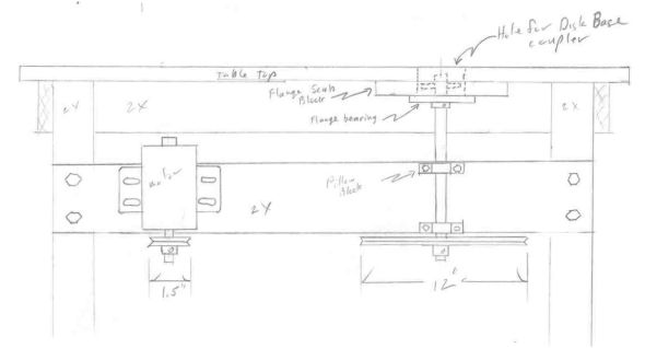
The overall plan is shown in Figure 1. If we assume that low RPM motors (1850rpm) are readily available then we want to reduce this to around 200 - 400 rpm. If we put a 1.5" pulley on the motor and a 12" pulley on the jack shaft that is an 8 to 1 reduction and 1850 ⇒ 231.25rpm.
Figure 1The design is made to keep all the weight of the sanding disk off the drive shaft, but we still want a pretty hefty shaft. In this case I chose a 1" diameter shaft (and the 12" pulley) because they were available free from my local Heating and Plumbing shop as a junk squirrel cage blower from a forced air furnace. So was the 1/3hp motor. I suggest that you also check out your local H&P shops because they are always throwing out these things from remodel and repair jobs. They are an infinite source of motors. The shaft is mounted with self aligning pillow blocks with locking collars. Since the shaft is vertical we want to use the locking collars to keep it in position, place the collars on the outside of each pillow block. The top end of the shaft is located with a flange bearing that is mounted to a scab block which is in turn attached to the bottom of the bench. This allows us to have a hole in the bench top large enough to receive pipe flange and pipe from the bottom of the hollow Form itself.
Notice that the diameter of the pulley is just about right for the setback under the bench to clear the leg. This will leave the hollow Form flush with the front edge but overhanging the side and should allow good access.
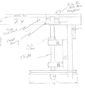 Figure 2
Figure 2 shows a front view of the same thing. The top end of the shaft is just below the table top so that nothing is protruding above the table. If desired one can make a plug for the hole to cover it when not in use. The shaft has a cross pin, I suggest a ¼” or larger roll pin. This will stay in place and can be replaced easily if necessary.
In Figure 3 is the layout for the hollow Form and drive link. In the interests of cost I have designed this with plumbing parts but ideally this coupling should be made by a machine shop in order to get everything in alignment. If you make it yourself I suggest that you first drill the inside to be
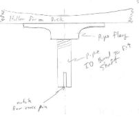 Figure 3
exactly 1", then slip it over the 1" shaft with the pipe flange attached and spin it up and face off the surface of the flange to get it flat. If you don't have it pretty flat it will make the whole hollow Form wobble when it spins, not a good thing.
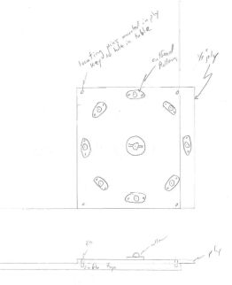 Figure 4
Before cutting the pipe to length and making the slot for to fit over the roll pin we need to decide on the length of the pipe. So Next we need to make the support for the hollow Form. Figure 4 shows an option for this. Take some ¼” ply or hardboard and mount a ring of out-feed rollers. I used the kind that are a large captured ball bearing so I didn't have to worry about exact placement. Since I want this to be removable I decided to mount some ¼” dowel pins in the board that key into holes in the table top. That way I can just key it into position and hold it down with a couple small clamps at the edge. This board will overhang the edge of the table so it must be stiff enough to support your hollow Form. You may want to go with ⅜” ply. Another aspect of this is that the bottom of the hollow Form where it rests on the rollers may wear after a while, this remains to be seen. If this is a problem then a thin layer of sheet metal could be attached to the hollow Form.
The last step is to cut the pipe to length. Just rest the hollow form on the rollers and measure from the bottom of the disk to the table top. Add to that measurement the distance from the table top to below the roll pin on the shaft and this is your cut length. Then cut a slot in the end of the pipe to receive the cross pin. Since the disk doesn't have any airfoil for lift I don't think that any additional locking slot is needed.
My hollow forms are made up double thick from two pieces of 3/4" MDF glued together. You may want to make your forms for the sander this thick too for extra stability. You will need at least two disks, one for the top and one for the back, so you may want to make multiple pipe and flange attachments and just leave them on the disks. Otherwise they can have the screw holes slotted so that a single attachment can be moved between disks.
Parts:
The following parts numbers and prices are taken from the 2002 Grainger catalog. I am using these as exemplars, not necessarily the only things that will work.
Item & Qty. |
Description |
Grainger # |
Mfgr. # |
Price |
Flange Bearing (1) |
two bolt self aligning VF2s 100 series, set screw locking. 4 19/32 bolt centers. pp344 |
5X708 |
Browning VF2S-116 |
$26.20 |
Pillow Block (2) |
cast two bolt rigid, VPS 100 series, set screw lock, 4 1/8" centers. pp344 |
6X235 |
Browning VPS-116 |
$26.20 |
Pulley - Motor (1) |
1.5" OD, 3/8 - 5/8" ID die cast. pp318 |
½" - 3X892 5/8" - 3X893 |
|
$2.39 |
Pulley - Jack shaft (1) |
- 12" OD, 1" ID - 14" OD, 1" ID |
- 3X941 - 3X943 |
|
13.87 17.85 |
Drive Belt (1) |
Notched 3VX type from pp317. Estimate length at ≈54" |
|
|
$15.40 |
Drive Belt (optional) |
Link type low vibration belt. 6' length. pp317 |
5A548 |
|
$35.80 |
Motor (1) |
1/3hp minimum, 3/4hp or above suggested |
|
|
|
The 1" diameter shaft can be purchased as needed. See suggestions above about dumpster diving for the motor, shaft, and pulleys at a local Plumbing and Heating shop.
Implementation: (Circa May of 2006)
As with most of my designs, what I end up building gets designed along the way and morphs into a new design. About the time I'm all done I realize how it should have been designed but usually never get around to going back and doing it again.
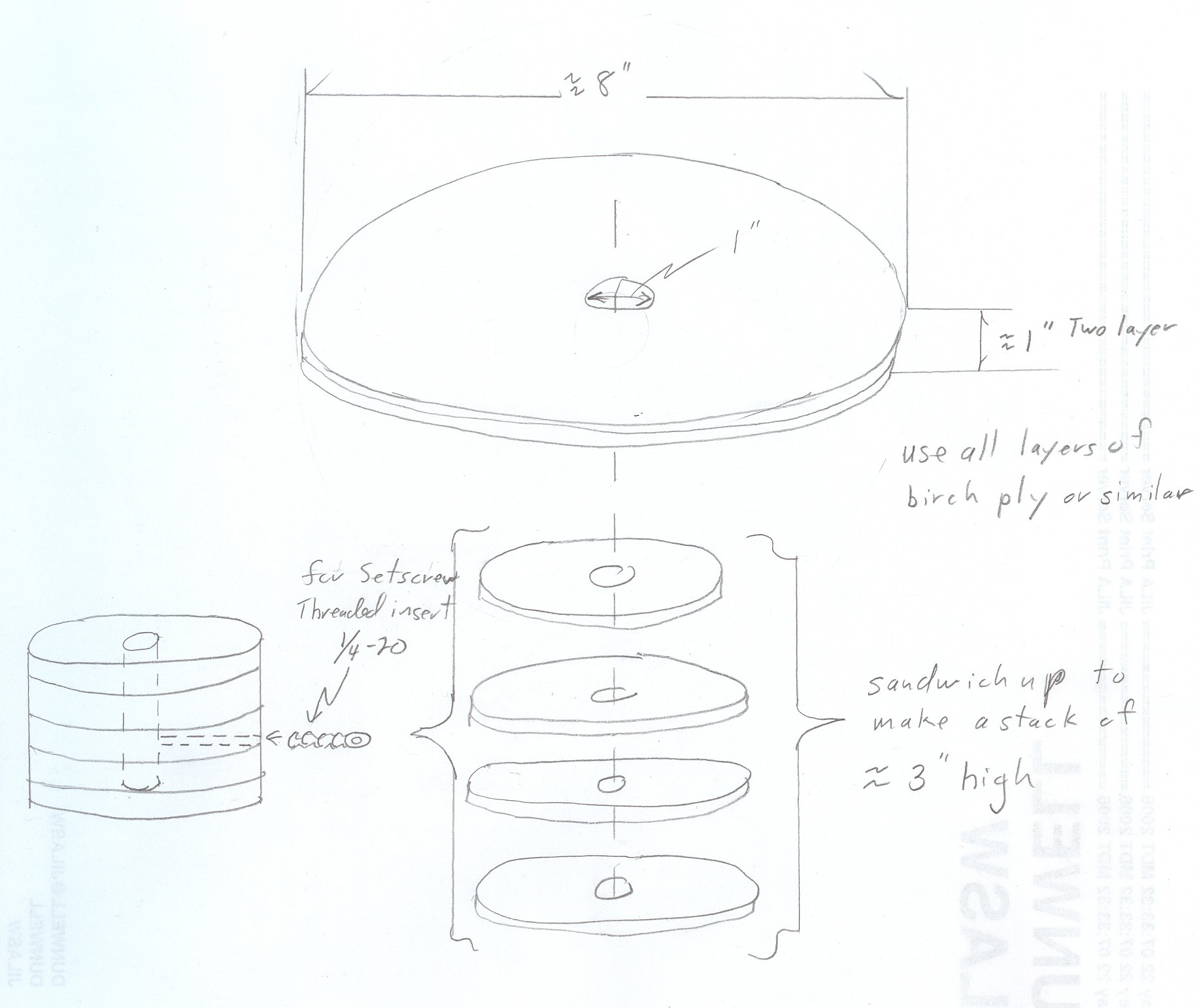
I kept the basic design but realized that installing it into my regular workbench would have placed it too high up for comfortable use. Instead, I built it into a small, low table that I already had that lives behind my tablesaw. The same rules applied though that I wanted to be able to use the table as a table when not sanding. The second change was to make the top hub solid to the shaft but flush with the table top so that when the hollow forms were not in place it was still just a smooth table top that could be used for other purposes.
The key to these changes was a cast iron lathe face plate. These are throw-away face plates designed to be used on a lathe for one-of jobs. You chuck up the back part of the hub and then you can drill and screw things to the face part and turn them. When it is all drilled up or otherwise no good it is tossed out to recycle. So they are cheap. In retrospect this item is overkill. It doesn't need to be that heavy a piece of material. Also, the center 1" hole was not really true, it was a cast or rough turned hole, not a true bored hole. So I ended up having to bore it out more on a lathe and insert some bushings. Clearly not an option for most folks. However the same design hub could be made up by cutting out rounds of birch, european, or marine plywood and gluing them up in a stack. Then drill a true 1" hole on a drill press for the center. Then drill a hole for a setscrew and put a threaded insert in there. All easily done in the woodshop and plenty strong enough for the purposes of this device. I would recommend gluing up the small stack first, drilling the 1" hole, then drilling and installing the 1/4x20 threaded insert for the set screw(s). Then glue this small stack to the larger 8" disk and finally drilling the 1"hole using the small stack as a guide. I think it will be easier to get the threaded insert in at a true 90 degrees to the shaft this way.
Note also that this design now makes the hub and the disk very solid and we can eliminate the top flange bearing and the support plywood sheet with the rollers all together. I never liked that anyway. That leaves us with just the two locking pillow blocks (now about $32.00 each) and the shaft and pulleys. I used a 1" shaft, 12" pulley, and 1/4-hp motor from a throw-away fan from my heating and plumbing shop. Note that you need to file flats onto the shaft where ever a set screw goes, or else the set screw will burr the shaft you will never ever in this lifetime be able to disassemble it.
Here is a photo of the underside of the table as I am using and the drive setup.
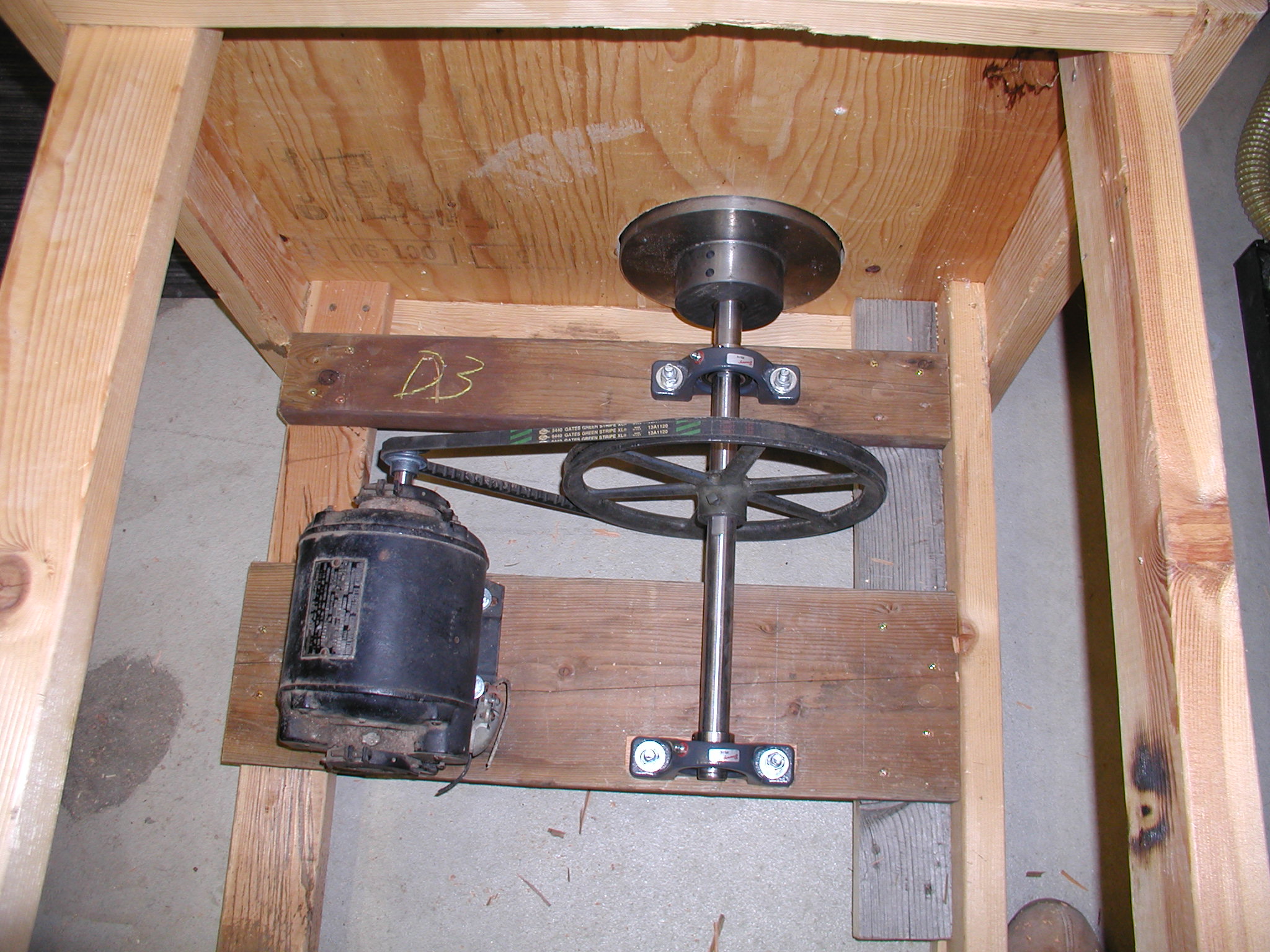
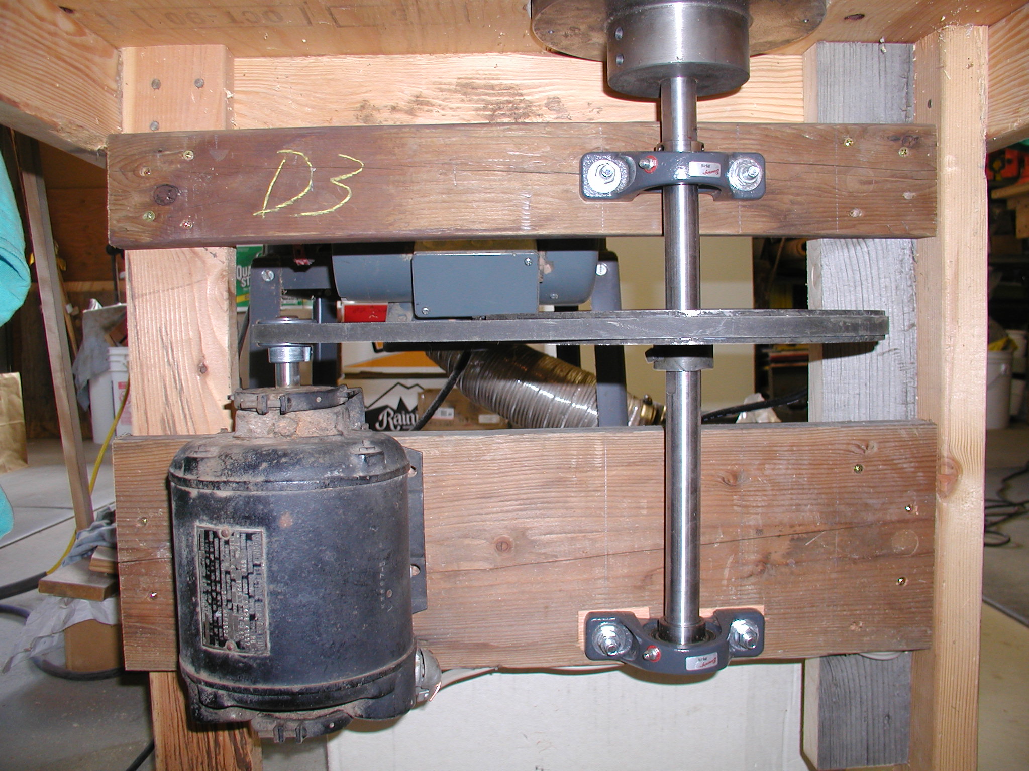
As you can see I've moved the drive pulleys up to the center, it seemed a bit safer there what with my OSHA approved setup. I cut a hole in the top of the table that is just large enough to allow the hub to go through with minimum clearance so as to preserve as much of the table top as I can.
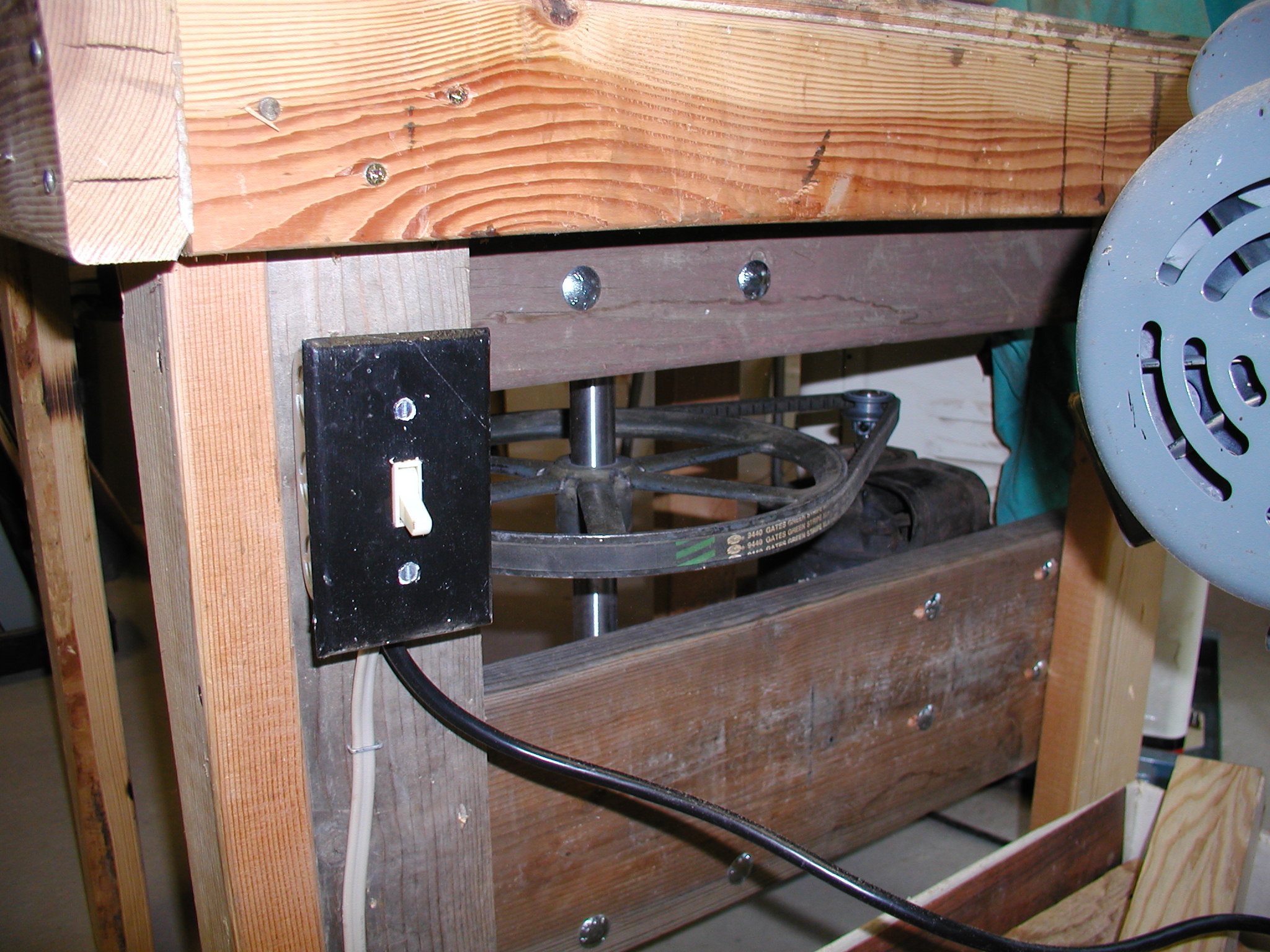
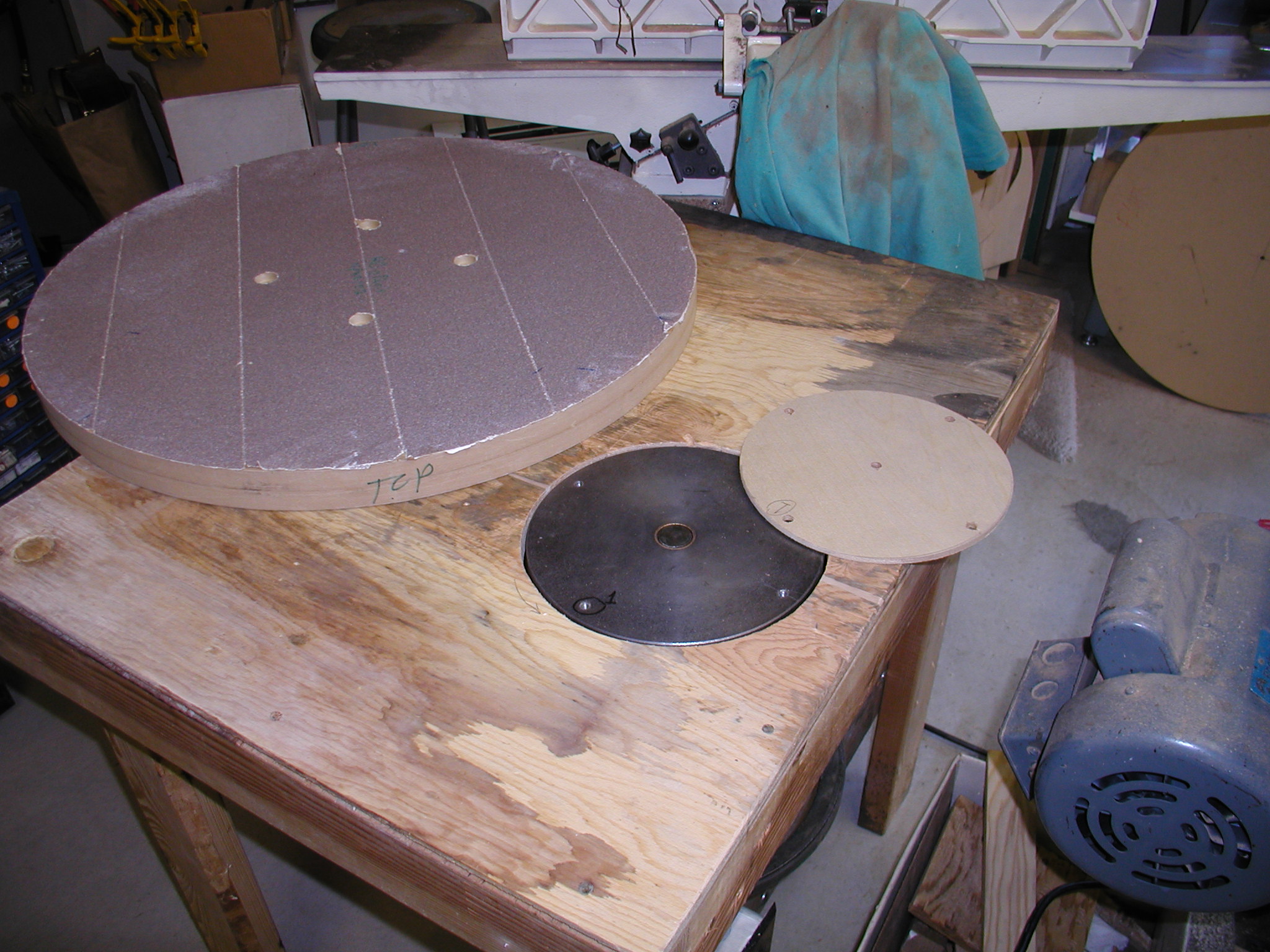
Power is just through a regular wall switch since it is just a 1/4-hp motor it doesn't draw much current. Notice the top of the hub is set in flush with the top of the table and is drilled with four 1/4x20" bolt holes. I then made a simple spacer of 1/4" plywood to give clearance from the table top. The sanding disk is also drilled with four 1/4" holes and is counter sunk to allow the bolts and flat washers to be recessed.
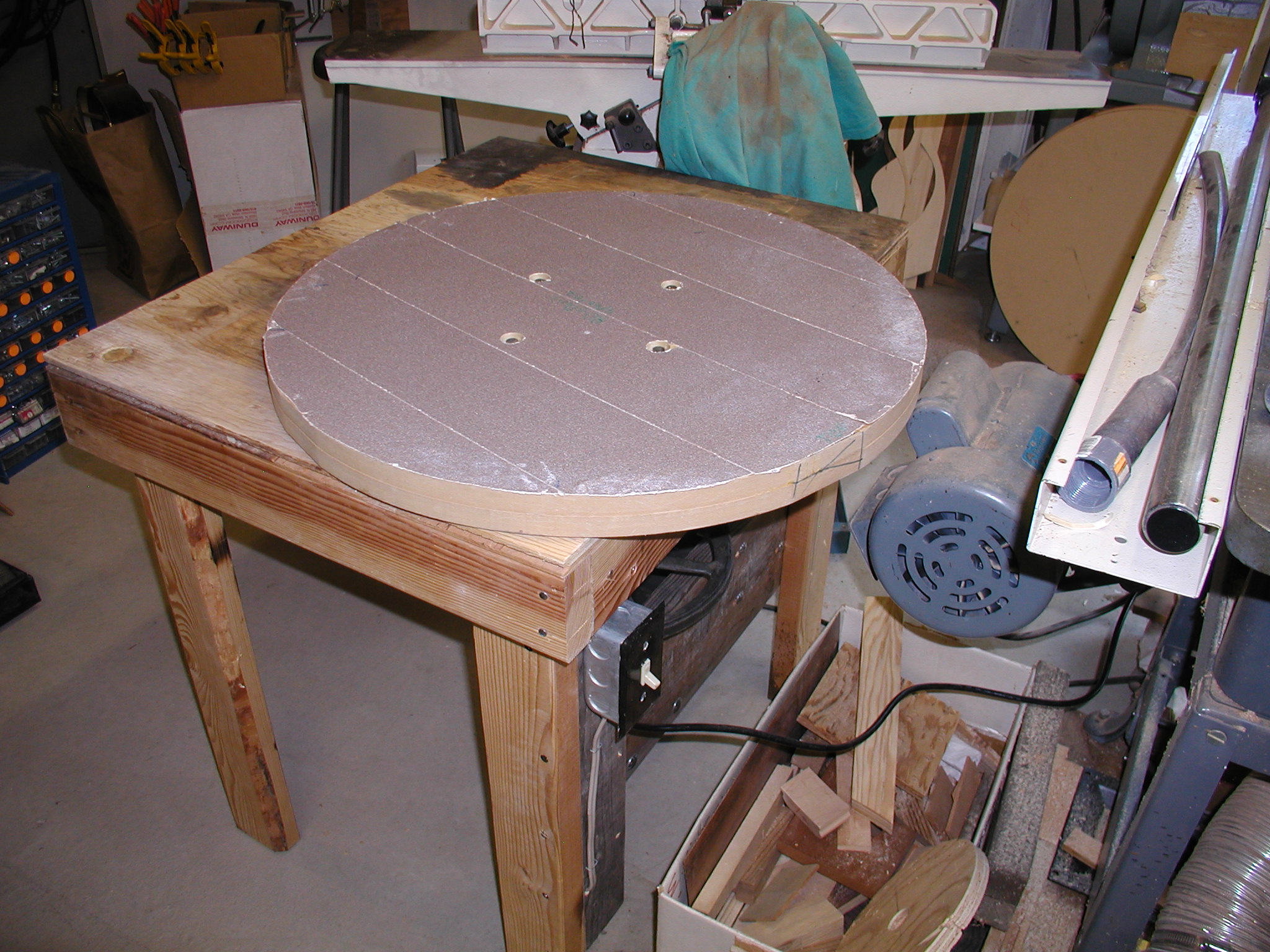
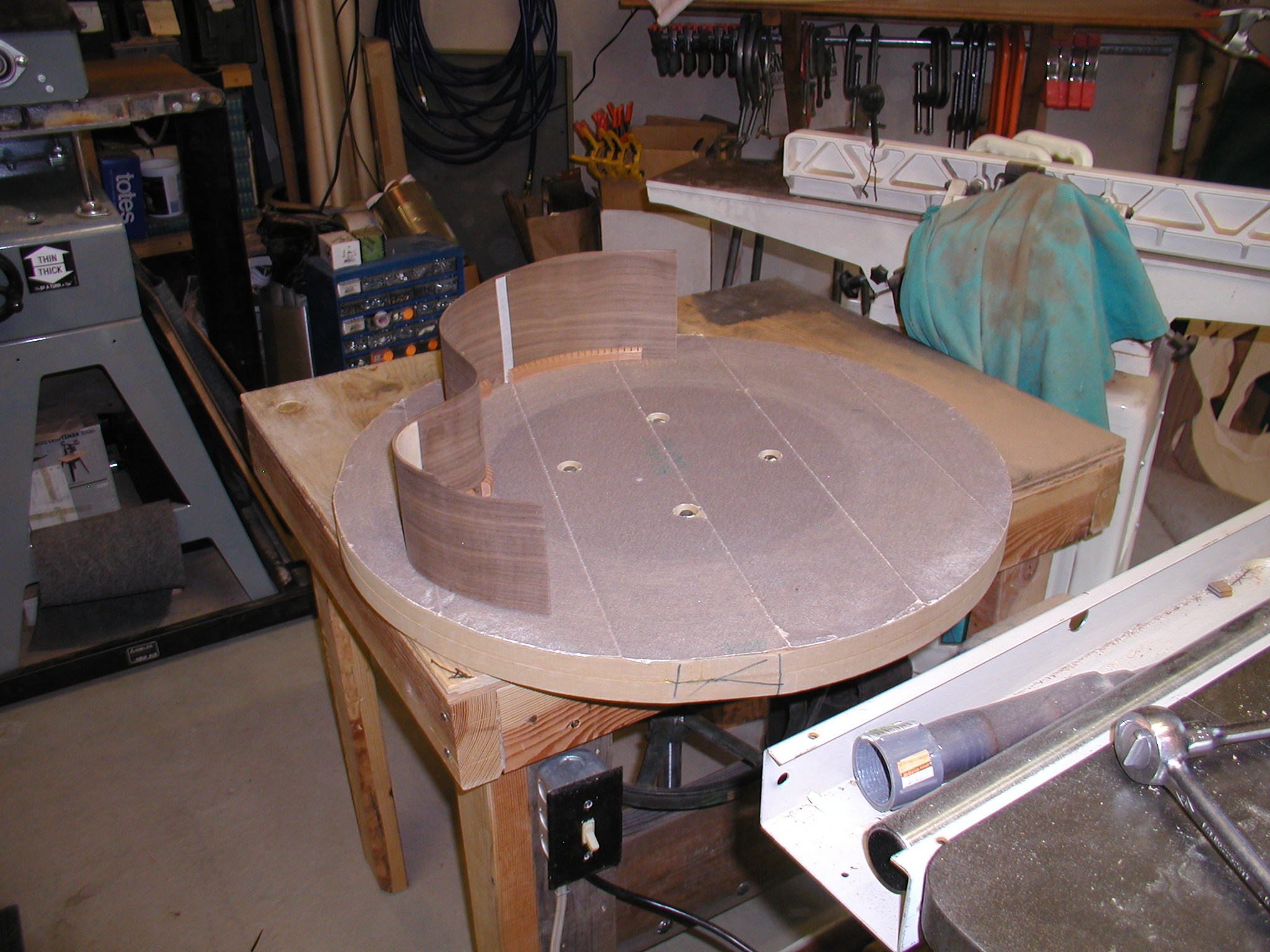
Here it is all assembled and where I am sanding the linings and sides true to the form. The speed is nice and slow and doesn't throw much if any dust. I still set a pickup from my vacuum system on the back side of the table to catch any airborne stuff that comes off but it isn't much.
Since the motor is only 1/4-hp I also give it a bit of a spin when starting up just to avoid the current surge, but it really doesn't need it and it has plenty of power. Besides the sanding you are doing isn't loading it much at all anyway. It took me about 3 hours to actually build the thing once I had all the parts ready to go, but I already had the table in existence, so add in an hour or two for making that. The benefit in time is obvious straight away. Sanding the linings like I show above is about a 30 second process per side. Once I have the sides glued to the top, I take the whole assembly with a waist clamp in place and invert it to sand the sides and their back linings down true to the blocks. This took all of about a minute. This used to be a half hour to hour process when I did it by inverting the hollow form and wiggle sanding down to the blocks.
Another benefit is that the result is much better and a more accurate fit. I can hold the side very steady and just slowly press it to the rotating sandpaper so it not chattering or deforming while I do the sanding.